

Tools
If there is no menu bar on left - click here
The following tools and general techniques were used in the construction of my Falconar F11A aircraft.
SPAR PLYWOOD COST SAVINGS.
After building the Rudder, Ailerons, Stab, and Elevator, the wing spar was the next sub-assembly on the list. After carefully studying the plans, I noted that the spar plywood had to be cut at 45 degrees to the face grain. After a little more thought, I realized that there would be substantial waste plywood left over from this operation. The 4 sheets of plywood that I had already cut into small gussets could have yielded 8-10 full sized (about 5-6ft long each) pieces of spar plywood. (should be enough to cover 2 sides of the spar) If I had planned properly, and cut spar material from every sheet purchased to date, I would only need 4 more sheets to cover the entire spar. At this stage, I will need 8 more sheets. In Canada, 60"x60" sheets of Finnish birch plywood costs about $60. I may have just wasted $240! After cutting the spar pieces from the 8 plywood sheets required, the waste pieces would have provided more than enough material to cover the gusset requirements. Isn't hindsight great!!! I hope this tip will help someone. (this tip only applies to those who wish to minimize the number of scarf's in the wing spar plywood, like me)
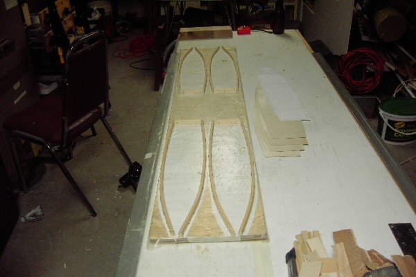
SPAR JIG
With the workspace available, I could not build the wing spar jig recommended in the builders manual, however, a variant of the concept could be built. The "U" shaped mini-sawhorses (seen below) were made from an old melamine shelf but could be made from plywood or similar material. As the parts are wood, the internal surfaces will be covered with duct tape to avoid having a portion of the jig becoming a permanent addition to the aircraft spar. Gray duct tape is a very good release agent for epoxy.
The "U" shape internal dimensions are 258mm x 200mm. The internal dimensions were selected to account for the width of the spar (250mm), the added thickness of 2 layers of 1.5mm plywood (253mm), and a little room left over (5mm) for some shims. The top of the jig uprights extend over the top of the wing spar. This will allow for the addition of wires, ropes, or bungee cords to stop the uprights from spreading when the sawhorses are used to help clamp the plywood to the sides of the spar. A cross brace may be installed across the top of the uprights to allow the clamping of the top plywood (with shims).
The sawhorses are built as a tripod. The tripod shape is inherently stable and will eliminate the wobble that is possible with 4 feet. The entire jig is leveled by removing small amounts of material from the individual sawhorse feet (by sanding). When the time comes to add the ribs to the spar, the feet will be removed (simple screws) and replaced with longer parts. The dual foot will have to be proportionally wider to increase the stability of the taller jig. The sawhorses can be built full sized right from the start but I chose to go with the lower, and inherently more stable position first. In my opinion, the cost and time savings of bypassing the lower sawhorses does not offset the additional difficulties adjusting, and dealing with the instability of a taller jig.
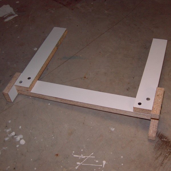
WORKBENCH
With the workspace available, I could not build the workbench recommended in the builders manual, however, a table measuring 2ft x 8ft was possible. A standard 4'x8' - 3/4 " single smooth sided plywood was cut down the center lengthwise and painted white with flat (non-gloss) water based paint. On each long side, a 1"x2" was affixed As can be seen in the picture above, I recycled two angle-irons and screwed them to the sides of the workbench. These angle-irons ensure that the table is absolutely level and will not bow under the weight of the tools and jigs. The angle-irons have a secondary benefit. As they protrude from the table top by about 3/32", they provide a straight edge that I use to ensure the alignment of long parts, (eg.- aileron or elevator spars) A set of typical folding legs were attached.
I built the parts on the tabletop using the following technique:
A - Using the straight edge of the angle-iron as a starting point, carefully measure and draw the shape to be built on the table top. If the table surface is rough, lightly sand the surface, as required, to get a smooth, level finish. Remove all residue.I found this technique resulted in accurate, repeatable parts with a minimum of hassle and expense.
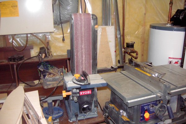
A decent belt sander. Possibly the most useful tool in the shop. As can be seen in this picture, the final assembly and fitting of each piece of lumber requires care and attention. This tool allows accurate angles to be sanded to ensure a flush fit. If these angles were hand sanded, it is likely that the sanded faces would be somewhat rounded, reducing the effective flush contact area at the joint.

A good table saw. Some of the parts have to be trimmed to specific angles as can be seen here. Cutting a consistent angle over a length of 8 or more feet would be a major challenge without the right tool and jig.

A home-made sanding board. To ensure straight parts, a long sanding board is required to span fairly large surfaces. This one was made from scrap materials. The sanding board will get lots of use so I made sure I could use it comfortably.

An alignment laser. To ensure straight parts, I found that a laser capable of projecting a vertical and/or horizontal line is a great tool. It is not absolutely required to build the aircraft but for $30, including tripod, it is a very inexpensive way to improve the overall quality of the final product.