Falconar F11A Wing Spar
If there is no menu bar on left - click here
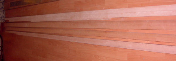
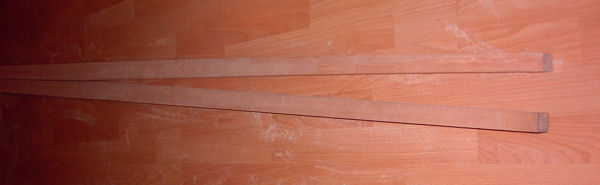
| An acquaintance paying a visit noticed my aircraft and mentioned that he had some 10 year old Sitka Spruce planks in his barn and wanted to know if I wanted to take them off his hands otherwise they would become firewood. A quick look at this lumber and "WOW"; Three 2"x6" - 16ft long, aircraft quality pieces!! While the surfaces are somewhat marred by 10 years in a barn, the wood grain looks perfect!! I wont know for sure until they pass through a planer but I think I have the wing spars for my Falconar F11A! |
Click to see full size.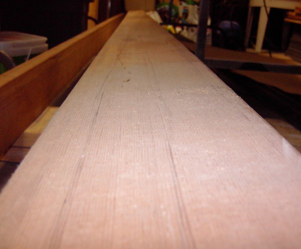 Click "Back" button to return to this page. |
|
| Jan 15th, 2007 12hrs - 232hrs total. |
Work on the spar has started. The three 2"x6" - 16ft long boards were planed and carefully examined. Several flaws were noted as can be seen in the images to the right: The first board has a hairline crack running across the width of the board, about 9 feet from the end. |
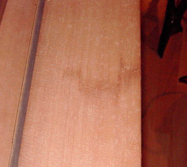 |
| The second board has a single knot that corrupts about 1/3 of the width. |
 |
|
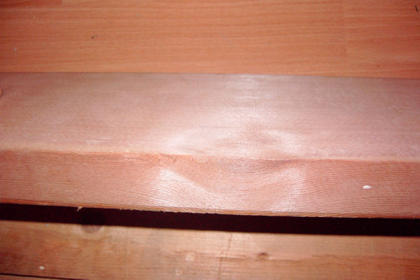
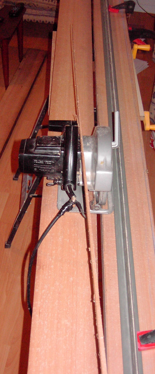
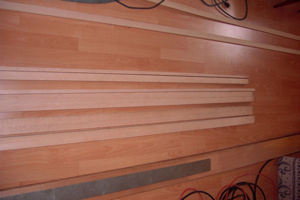
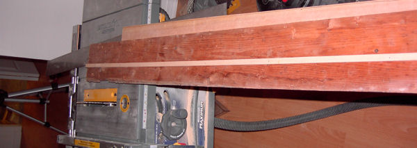
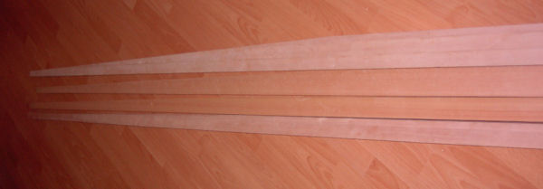
| The last board has a grain run-out of about 1-100. While this is acceptable according to the military specifications for aircraft spruce, I would prefer no run-out. Since the lumber is just wide enough, the spar flanges will be cut out on an angle, following the grain. The tapered strip from the first cut lies on top of the circular saw in the image To the right. With this strip removed, the two spar flanges will be cut on a table saw. There should be little, if any, run-out remaining in the final products. As a firm believer in the principle of belt and suspenders, I installed a fence to guide the saw. Additionally, I scribed a cut line, and a "no trespass" line. The "no trespass" line represents the final dimension of the spar flange. I wanted to ensure that if the saw blade deviated slightly, I had a warning line that I should "not trespass". Once the flanges are cut, they be planed to the final dimensions. The lines were made with a chalk line and verified by laser. With such a small workshop, only our recreation room can support the machining of 16ft long lumber. While I might consider the activity of machining this lumber "recreation", the minister of health and welfare, (my better half) is not convinced that it belongs in our rec room. However, as she is presently tolerant and supportive, I will try not to test the limits of her tolerance....any more than I usually do. :-> |
 |
|
|
Jan 18th, 2007 6hrs - 240hrs total. |
Work on the wing spar continues. In the picture to the right, the raw material has been machined to form the 4 corner flanges. Due to the quality and damage to the raw material (mentioned previously), 2 of the 4 flanges will be made from laminations. In the picture To the right, starting at the bottom, the 50mm and 66mm solid flanges are shown. The 80mm flange is made up of 3 laminates, and the second 50mm flange will be made from two laminates. After gluing, the laminated flanges will be planed to the final thickness. |
 |
|
Jan 19th, 2007 3hrs - 243hrs total. |
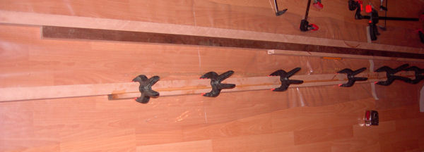
Work on the wing spar continues. In the picture To the right, the 50mm spar flange has been glued. The actual piece is oversized in all dimensions and will be planed and trimmed to its final shape after it has dried. In 48 hours the test pieces made from the same raw material as the spar, and from the same glue batch used in this flange, will have cured and can be tested. If the test pieces are good, I will proceed to glue the 80mm flange |
 |
|
Jan 21st, 2007 8hrs - 251hrs total. |
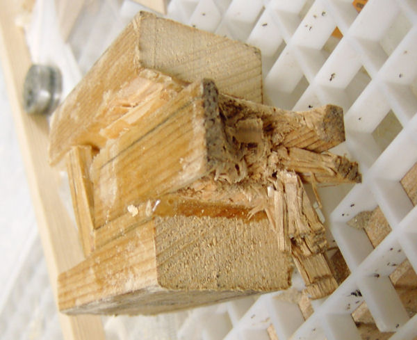
Work on the wing spar continues. I tried to crush one of the test pieces in a vice as per my normal practice but the part refused to break. I reverted to plan "B" and a few dozen well placed hammer blows later....... I think the glue batch was good. |
 |
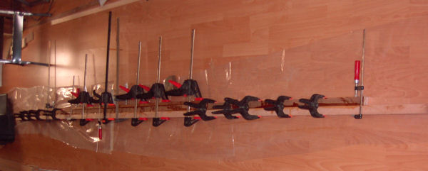
| The 80mm spar flange was glued. |
 |
|
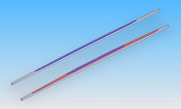
| And both flanges were planed. Remaining to do: Trim a taper into the parts as can be seen in the rendering to the right. |
|
|
|
Jan 22nd, 2007 8hrs - 259hrs total.
|
Work on the wing spar continues. The first step in cutting the taper in the wing flanges is the construction of a jig. My jig consists of a simple board (very straight) to which is attached a guide that fits snugly into the table saw miter gauge slot. It is very important that this guide be parallel to the edge of the board. |
 |
|
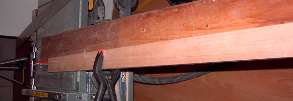
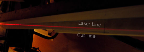
With the jig turned right side up and inserted into the table top miter gauge slot, the flange is positioned on the jig. With the required cuts marked on the flange, carefully align the front (table saw side) of the flange to the blade of the table saw and temporarily hold it in place with a clamp. Measure the distance between the laser line and the cut line on the front of the flange (table saw side). Adjust the flange so that the cut line is equal distant and parallel to the laser line. On my setup, there was exactly 1/2inch separating the cut line and the laser line. Mark the final location of the flange onto the jig. To securely attach the flange to the jig, I used double sided tape as clamps can not be used when the over half the jig and flange is pushed through the table saw. After cutting one side, flip the flange end to end and position the new end into the markings made earlier. Make sure both tapers are cut on the same side of the flange. (I came really close to making this error) |
 |
|
|
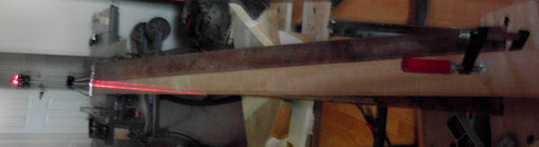
Shoot a laser line down the entire length of the edge of the jig (table saw blade side). Sorry for the picture quality but after 45 minutes of trying, this is the only picture that faintly showed the laser line running down the entire left edge of the Jig. |
 |
|
| I cut the flanges slightly oversized and will sand down to final dimensions. Two flanges are completed, two are left to go. |
 |
|
|
Jan 22nd, 2007 - Continued 4hrs - 263hrs total |
I messed around with the laser and camera some more, here is a better picture. |
 |
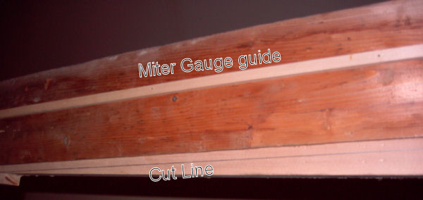
| An alternate method of aligning the cut line to the miter gauge guide would be to work from the back of the jig as can be seen To the right. Measure the distance between the saw blade and the miter gauge slot on the table saw. Using this measurement, place the flange on the jig so that the pre-drawn cut line is the same distance away from the jig's miter gauge guide. In hindsight, this method may have been easier, but I would not have enjoyed messing with the laser. |
 |
|
| Machining of the spar flanges is completed!! (thank god.......) Now to start on the wing spar diaphragms. |
 |
|
|
Jan 24th, 2007 6hrs - 269hrs total. |
Started on the wing spar diaphragms. I first had to pick up some Ash as the plans call for a 30mmx40mmx126mm piece of ash. Note to self - Think twice before you speak. Never ask your wife where she thinks you could pick up a nice piece of ash. I dragged my bleeding carcass into the local hardwood supplier and got a good deal on a small off-cut that will be big enough to do about 1/2 of the aircraft. ($1.69) To the right is the first diaphragm (-4) dry fitted. |
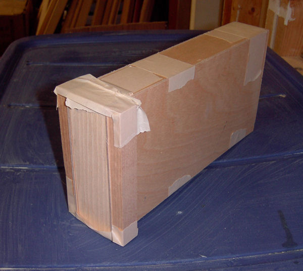 |
| And the second is drying. |
 |
|
|
Jan 26th, 2007 6hrs - 275hrs total. |
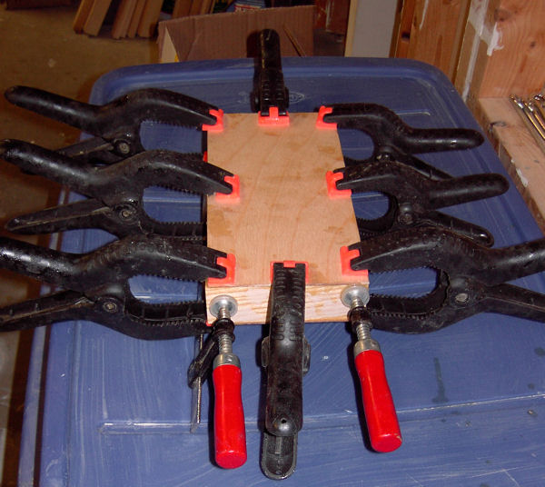
To the right are the next three diaphragms to be glued. |
 |
| It is important to make sure that the diaphragms are square |
 |
|
|
Jan 27th, 2007 6hrs - 281hrs total. |
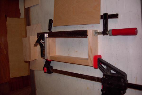
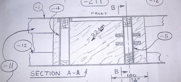
Work on the Falconar F11A wing spar diaphragms continues. The diaphragms are glued and cleaned. These 4 diaphragms make up the fuselage and gear attachments points. To the right is the right hand wing and fuselage attachment diaphragms being dry fit. The left hand diaphragm in this photo is for the fuselage attachment and the right is for the gear. The plywood at the top of the picture fits on the top of this assembly. One thing to remember is that the plywood is installed at 45 degrees to the grain. The left hand assembly plywood must be installed as a mirror image. (eg . the right hand plywood is at 45 degrees, then the left hand plywood would be at 315 degrees.) |
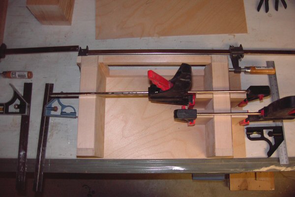 |
| They are supposed to match the dwg: |
 |
|
| Both left and right wing diaphragms are a work in progress. |
 |
|
|
Feb 01st, 2007 5hrs - 286hrs total. |
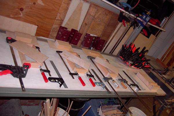
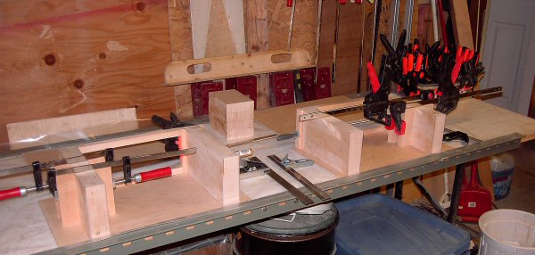
Work on the Falconar F11A wing spar continues. The diaphragm assemblies are glued. The "-3" diaphragms are completed (4 smaller rectangles at each end of the spar) . |
|
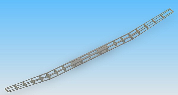
| To the right is the first dry fit of the wing spar. Everything looks very good! The next step is figure out a jig that will provide a guaranteed straight and level surface for the final spar assembly and gluing. |
 |
|
|
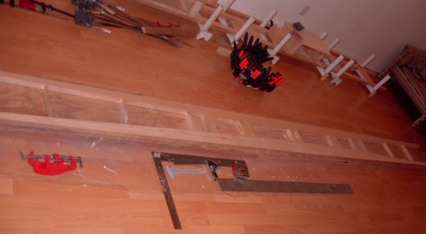
Feb 04th, 2007 9hrs - 295hrs total. |
Work on the Falconar F11A wing spar continues. I decided to use a technique similar to one described in the builders manual. I built miniature "U" shaped sawhorses (see tools and techniques page for details) which allowed me to make adjustments to remove variations in the floor. Using the laser, I shot a laser line across the base of the entire jig and marked (on the sawhorses) the portions that were not level. A little sanding of the sawhorse feet and voila, a perfectly level work stand. |

|
|
Feb 13th, 2007 8hrs - 303hrs total. |
Work on the Falconar F11A wing spar continues. After many attempts to control the elements that make up the spar within the jig described above, I finally had to admit that this was not a very efficient method. In order to ensure that the spar is built to exact dimensions, all elements that make up the spar must be controlled in all three dimensions. As I dry fitted everything together, preparing for glue, I would position a part exactly where it belonged, and move to the next piece. By the time I would be finished positioning the last piece, the first pieces had moved and I would have to restart. If I really tighten the clamps, the parts would not move but I knew that the clamping pressures were too high for epoxy and I would get dry joints. So after a few hours of messing around, and a few pauses for gratifying cursing, I finally went back to the drawing board. While the existing wing jig is not very useful to glue the individual elements into a spar, it will be indispensably to attach the wing extensions, and the spar covering plywood. The new jig may be described as a mastery of recycled thought and purpose. I took a 4'x8' sheet of 3/4" plywood, (finished on one side) and cut it into 4 - 1'x8' lengths. These lengths were nailed together to form a 1'x16'x1.5" work platform. I carefully drew the exact shape of the upper flanges, diaphragms, and spacers on this work platform and covered the entire surface with plastic sheeting. 2 inch nails were nailed around the periphery of the drawing. The nail heats were then cut off. After inserting the parts to be glued, the nails were slightly bent (leaned) to finalize the exact position of each element. At the time of this web update, I am about to glue the parts together. If this process sounds familiar, then you know that this is the same method that was used to build the vast majority of parts. After the upper and lower flanges are glued, they will be reinstalled in the "U" shaped sawhorses for the final forming of the wing spar. |
 |
|
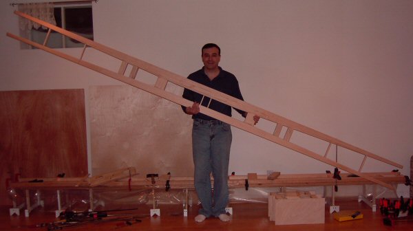
Feb 18th, 2007 9hrs - 312hrs total. |
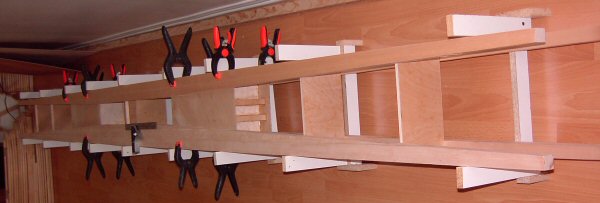
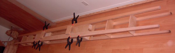
Love these wooden aircraft! The upper spar flanges came out perfect. I included myself in this picture to provide a size perspective. This upper flange measures about 4 meters (13 ft) long. In the background, the lower flanges are being fit. |
 |
|
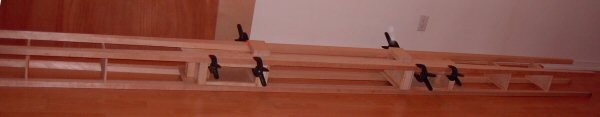
Feb 28th, 2007 12hrs - 324hrs total. |
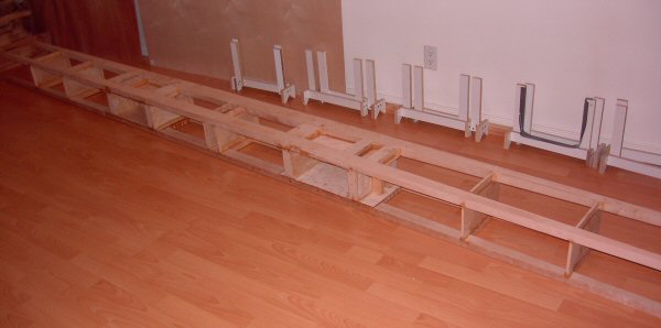
Work on the wing spar continues. The upper spar flange was cleaned and set aside. The jig was rebuilt (new drawing, new nails, etc) and the parts were fitted, trimmed and glued. After drying, the lower spar flange was removed from the jig and the excess glue sanded. The lower spar flange assembly was installed in the mini-U shaped sawhorses and the diaphragms were fitted, and glued. As of today, the entire assembly is back in the mini-u shaped sawhorses being dry-fit. As can be seen, I have yet to sand the excess glue from the installation of the diaphragms. |
 |
|
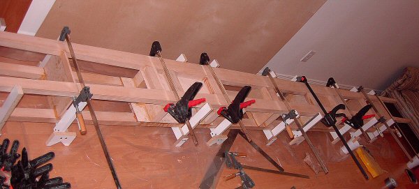
Mar 11, 2007 13 hrs - 335hrs total |
Apart from some sanding, and applying the covering plywood, the center spar is done. I have decided to bypass the construction of both wing extensions since my better half is resistant to the concept of jacking up the house to get my aircraft out. (Never could understand women!?!) The center spar will go into storage while I start on the fuselage subcomponents. |
|